File menu
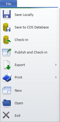
The File menu of the document editor contains the following commands.
Save Locally
This command saves the open document in your workspace. The document stays open.
Nobody else can see your modifications.
You can still undo your changes with the Cancel Checkout command of the Document browser.
Save to COS Database
This command saves the open document in your workspace and updates your modifications to COS. The document stays open.
After this, other designers can see the document and your latest changes in it, and the document will be included in COS backups, but you still have the ownership.
If you are working on an online replica, the document files are replicated to all master sites above your site and the document can be browsed at these sites (on the following day at the latest).
You cannot undo your changes with the Cancel Checkout command of the Document browser.
Note: The document object is saved independently from the area model where it is being worked on. If you have routed a pipe that is not stored to COS yet, you can create a drawing that shows the pipe. If you then save the document to COS and somebody else opens it, the pipe does not exist in COS yet and therefore it is not visible in the drawing views. In situations where something like this might happen, Plant Modeller tries to notify the user: for example, when you start to edit a document, Plant Modeller checks whether your changes to the area model are saved to COS, and whether changes made by others have been updated to your area model. If the program finds any need for an update, then you prompted to synchronize the data.
Check-in
This command closes, saves, and checks in the open document.
The document is saved to COS, the working copy is removed from your workspace, and another user can check out the document and continue working on it.
If you are working on an online replica, the document files are replicated to all master sites above your site and the document can be browsed at these sites (on the following day at the latest).
If there are unsaved changes in the open document, you are prompted to save those changes as well as the change control state of all pages.
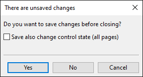
Select Save also change control state (all pages) if you want to reset the document's current record of changed and new model objects; the document keeps track of objects that are changed or created from this moment onward. If you do not select this option, the document keeps its current record of changed and new objects and updates the record with objects that are changed or created from this moment onward.
For more information on change control, see Visualization and Changes.
Publish and Check-in
This command closes, saves, checks in, and publishes the open document.
If there are unsaved changes in the open document, you are prompted to save those changes as well as the change control state of all pages.
Select Save also change control state (all pages) if you want to reset the document's current record of changed and new model objects; the document keeps track of objects that are changed or created from this moment onward. If you do not select this option, the document keeps its current record of changed and new objects and updates the record with objects that are changed or created from this moment onward.
For more information on change control, see Visualization and Changes.
Export
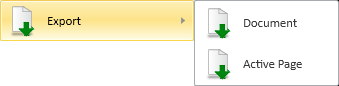
You can export the open document or just the active page to the file system.
Document | Active Page | Advanced settings | Using tags in document attributes
Document
You can export the currently open document in the desired format. If the document has multiple pages, you can choose whether to export it as one or multiple files.
Do the following:
-
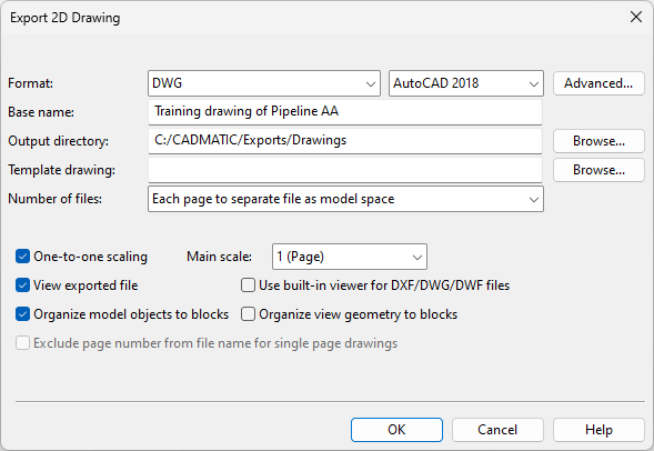
Select File > Export > Document. The Export 2D Drawing dialog opens.
-
Define the general export settings:
-
Format – Select the export format.
 Show/hide details
-
DWG – Select also which specific AutoCAD format to use.
-
PDF
-
DWF
-
DXF
-
SVG
-
PNG
-
BMP
-
JPEG
All formats except SVG have additional export settings.
-
For DWG or DXF export, click Advanced to define Advanced settings for DWG/DXF.
-
For PDF or DWF export, click Advanced to define Advanced settings for PDF/DWF.
-
For BMP, JPEG, or PNG export, click Advanced to define Advanced settings for BMP/JPEG/PNG.
-
-
Base name – The export files are named in the format <base name>.<page>.<file name extension>. The default base name is the name of the document object. You can edit the base name for single-file export.
-
Output directory – Click Browse to select the export folder.
-
Template drawing – For DWG and DXF export, you can select a DWT or DWG file to be displayed in the background of the exported pages. Click Browse to select the file to use.
-
Number of files – Select whether to export one file or multiple files. The available options depend on the export format.
Options for DWG and DXF export:
-
Each page to separate file as model space – Select this option to export one file per document page. Each file includes the contents of the corresponding page in Model Space.
-
Each drawing to separate file as paper layouts – Select this option to export one file per document object. This file may include multiple layouts (Paper Spaces), one per document page.
-
All drawings nested in a single file – Select this option to export all the included pages into the Model Space of a single file, arranged in rows or columns. Click Settings to define the Nesting Grid Settings.
Options for DWF and PDF export:
-
Each page to separate file – Select this option to export one file per document page.
-
Each drawing to separate file – Select this option to export one file per document object. If the document has multiple pages, the corresponding export file will also be a multi-page file.
-
All drawings to single file – Select this option to export all the included pages into a single multi-page file.
-
All drawings nested in a single file – Select this option to export all the included pages into a single-page file, arranged in rows or columns. Click Settings to define the Nesting Grid Settings.
Note: The PDF format has a maximum page size of 508 cm x 508 cm (200 inches x 200 inches). If the resulting layout exceeds this limit, the export will fail. If this happens, try reducing the Max cells per row or column value or exporting fewer drawings at a time.
-
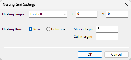
Nesting origin – Specify the origin point for the grid.
-
Nesting flow – Select whether to insert the cells in Rows or Columns.
-
Max cells per – Specify the maximum number of cells to populate in each row or column, depending on whether you have selected Rows or Columns.
-
Cell margin – Specify the amount of space to leave between the cells.
-
-
-
Define the other export options:
-
One-to-one scaling – Select this option to set the scale using the Main scale field, which lists the main scales common to the included drawings.
-
View exported file – Select this option to open the file or files after the export in the viewer associated with the file type. When Use built-in viewer for DXF/DWG/DWF files is also selected, the files open in CADMATIC Viewer instead.
-
Organize model objects to blocks – When selected, the export arranges model objects into blocks.
Note: Regardless of this setting, exporting to DWG or DXF places the data tables from the drawing sheet into blocks named using the format 'PageX_PAGE_SHEET_GROUP_TABLE_Y', where X is the page number and Y is the extension of the table. For example, the revision table (extension: rev) for the first page of the document is located in the block named Page1_PAGE_SHEET_GROUP_TABLE_rev. Additionally, any elements that are not symbols or data tables are assumed to be part of the title box and are therefore placed into the block named PageX_PAGE_SHEET_GROUP_TITLE.
-
Exclude page number from file name for single page drawings – When selected, page numbers are omitted from the file names of single-page documents.
-
-
Click OK. The file or files are exported into the specified folder.
Active Page
You can export the active page of the open document to a file.
Do the following:
-
Select File > Export > Active Page. The Export 2D Drawing dialog opens.
-
Define the general export settings:
-
Format – Select the export format.
Show/hide details
-
DWG – Select also which specific AutoCAD format to use.
-
PDF
-
DWF
-
DXF
-
SVG
-
PNG
-
BMP
-
JPEG
All formats except SVG have additional export settings.
-
For DWG or DXF export, click Advanced to define Advanced settings for DWG/DXF.
-
For PDF or DWF export, click Advanced to define Advanced settings for PDF/DWF.
-
For BMP, JPEG, or PNG export, click Advanced to define Advanced settings for BMP/JPEG/PNG.
-
-
Base name – The export files are named in the format <base name>.<page>.<file name extension>. The default base name is the name of the document object. You can edit the base name for single-file export.
-
Output directory – Click Browse to select the export folder.
-
Template drawing – For DWG and DXF export, you can select a DWT or DWG file to be displayed in the background of the exported pages. Click Browse to select the file to use.
-
Number of files – Select whether to export one file or multiple files. The available options depend on the export format.
Options for DWG and DXF export:
-
Each page to separate file as model space – Select this option to export one file per document page. Each file includes the contents of the corresponding page in Model Space.
-
Each drawing to separate file as paper layouts – Select this option to export one file per document object. This file may include multiple layouts (Paper Spaces), one per document page.
-
All drawings nested in a single file – Select this option to export all the included pages into the Model Space of a single file, arranged in rows or columns. Click Settings to define the Nesting Grid Settings.
Options for DWF and PDF export:
-
Each page to separate file – Select this option to export one file per document page.
-
Each drawing to separate file – Select this option to export one file per document object. If the document has multiple pages, the corresponding export file will also be a multi-page file.
-
All drawings to single file – Select this option to export all the included pages into a single multi-page file.
-
All drawings nested in a single file – Select this option to export all the included pages into a single-page file, arranged in rows or columns. Click Settings to define the Nesting Grid Settings.
Note: The PDF format has a maximum page size of 508 cm x 508 cm (200 inches x 200 inches). If the resulting layout exceeds this limit, the export will fail. If this happens, try reducing the Max cells per row or column value or exporting fewer drawings at a time.
-
Nesting origin – Specify the origin point for the grid.
-
Nesting flow – Select whether to insert the cells in Rows or Columns.
-
Max cells per – Specify the maximum number of cells to populate in each row or column, depending on whether you have selected Rows or Columns.
-
Cell margin – Specify the amount of space to leave between the cells.
-
-
-
Define the other export options:
-
One-to-one scaling – Select this option to set the scale using the Main scale field, which lists the main scales common to the included drawings.
-
View exported file – Select this option to open the file or files after the export in the viewer associated with the file type. When Use built-in viewer for DXF/DWG/DWF files is also selected, the files open in CADMATIC Viewer instead.
-
Organize model objects to blocks – When selected, the export arranges model objects into blocks.
Note: Regardless of this setting, exporting to DWG or DXF places the data tables from the drawing sheet into blocks named using the format 'PageX_PAGE_SHEET_GROUP_TABLE_Y', where X is the page number and Y is the extension of the table. For example, the revision table (extension: rev) for the first page of the document is located in the block named Page1_PAGE_SHEET_GROUP_TABLE_rev. Additionally, any elements that are not symbols or data tables are assumed to be part of the title box and are therefore placed into the block named PageX_PAGE_SHEET_GROUP_TITLE.
-
Exclude page number from file name for single page drawings – When selected, page numbers are omitted from the file names of single-page documents.
-
-
Click OK. The file or files are exported into the specified folder.
Advanced settings
In the Export 2D Drawing dialog, the Advanced button opens the advanced settings of the currently selected export format.
Advanced settings for DWG/DXF | Advanced settings for PDF/DWF | Advanced settings for BMP/JPEG/PNG
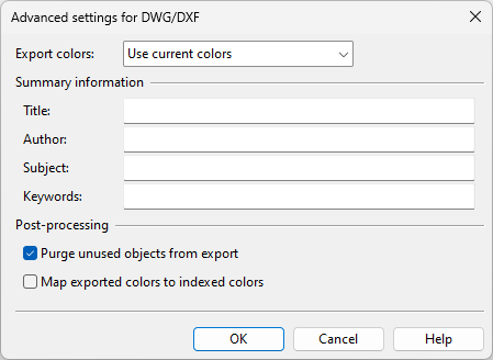
Advanced settings for DWG/DXF
-
Export colors – Select how to export colors:
-
Use current colors – Use the colors defined in the Layer configuration.
-
Black & white – Export everything in black and white.
-
Grayscale – Export everything in grayscale.
-
Custom current colors – Export everything in current colors except items that are defined to be exported in black and white. See Configuring export colors.
-
Custom black & white – Export everything in black & white except items that are defined to be exported in color. See Configuring export colors.
Note: If the drawing sheet or the drawing views contain objects whose color is white or close to white, they are exported in black color.
-
-
Summary information – Fill in the fields Title, Author, Subject, and Keywords. See also Using tags in document attributes.
-
Post-processing – Select post-processing options:
-
Purge unused objects from export – Select this option to remove unused objects (such as unused layers and styles) from the export data.
-
Map exported colors to indexed colors – Select this option to replace each exported RGB color with the closest indexed color. Indexed colors are used in AutoCAD, for example.
-
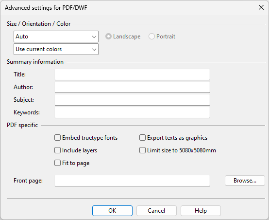
Advanced settings for PDF/DWF
-
Size / Orientation / Color – Select the page size, the page orientation (Landscape or Portrait), and how to export colors:
-
Use current colors – Use the colors defined in the Layer configuration.
-
Black & white – Export everything in black and white.
-
Grayscale – Export everything in grayscale.
-
Custom current colors – Export everything in current colors except items that are defined to be exported in black and white. See Configuring export colors.
-
Custom black & white – Export everything in black & white except items that are defined to be exported in color. See Configuring export colors.
Note: If the drawing sheet or the drawing views contain objects whose color is white or close to white, they are exported in black color.
-
-
Summary information – Fill in the fields Title, Author, Subject, and Keywords. See also Using tags in document attributes.
-
PDF specific – Select the required options.
-
Embed truetype fonts – Select this option to embed the fonts in the PDF file.
-
Include layers – Select this option to include the layers in the PDF file.
-
Fit to page – Select this option to fit oversized documents to the page size.
-
Export texts as graphics – Select this option to export texts as graphics (and not as text).
-
Limit size to 5080x5080mm – Select this option to set the maximum page size to 5080 x 5080 mm, to make the PDF file comply with ISO 32000. Content that exceeds the limit will be cut off, unless Fit to page is also selected.
-
Front page – Select a DWG or DXF file to use as the cover page of the PDF.
-
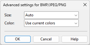
Advanced settings for BMP/JPEG/PNG
-
Size – Select the page size.
-
Color – Select how to export colors:
-
Use current colors – Use the colors defined in the Layer configuration.
-
Black & white – Export everything in black and white.
Note: If the drawing sheet or the drawing views contain objects whose color is white or close to white, they are exported in black color.
-
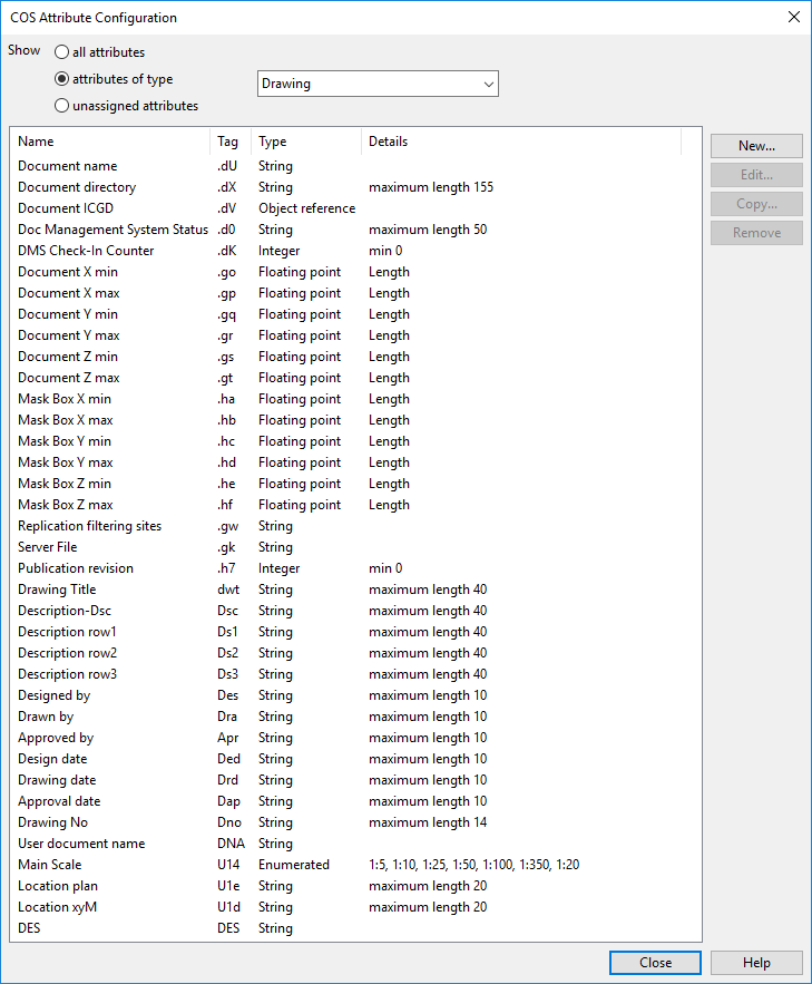
Using tags in document attributes
When exporting a Plant Modeller document in a format that allows specifying values for document attributes, it is possible to use tags within curly brackets in the attribute value fields: "{}". For example, to link document name to the title of the exported DWG or PDF, you can type something like "Document name: {.dU}" in the Title field. If the document name is "My Document", the title of the exported document would be: "Document name: My Document".
You can use the Manage COS tool to check which attribute tags relate to drawings and can therefore be used in document export.
You can print the open document or just the active page, or you can print a wireframe work view.
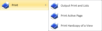
Output Print and Lists | Print Active Page | Print Hardcopy of a View
Output Print and Lists
You can print all the pages of the open document. Each page is printed to a separate file. If the ICGD of the document defines listings, the command saves them in the location defined in the shared settings: General Drawing.
Do the following:
-
Select File > Print > Output Print and Lists. The Print Setup dialog opens.
-
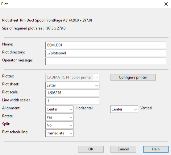
Specify the printing options and click OK. The Plot dialog opens.
-
Define the plot settings:
-
Name – Enter a name for the document.
-
Plot directory – Define the directory to use for the plotting files.
-
Operator message – Enter a message for the operator.
-
Plotter – You can open the printing options by clicking Configure printer.
-
Plot sheet – This is automatically set based on the paper size selected in the printing options.
-
Plot scale – This is automatically set based on the paper size selected in the printing options.
-
Line width scale – Define how to scale the line widths. Values between 0.5 and 1 make the lines thicker, and values larger than 1 make them thinner.
For example, when a larger sheet size is scaled to fit on a smaller paper size, thinner lines make the document easier to read.
-
Alignment – Select how to align the document horizontally and vertically.
-
Rotate – Select whether to rotate the document.
-
Split – Select whether to split the document.
-
Plot scheduling – Select whether to plot immediately or later.
-
-
Click OK. The Save Print Output As dialog opens.
-
Select the saving location, enter the file name, and click Save.
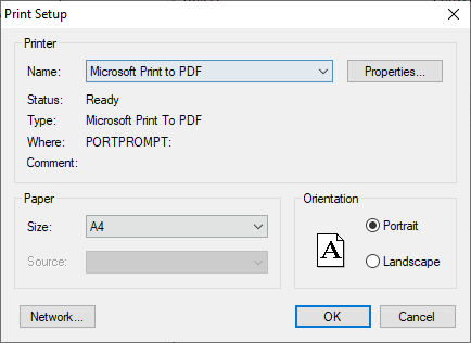
Print Active Page
This command opens the Print Setup dialog for printing the active page.
Print Hardcopy of a View
This command allows you to select an open wireframe work view and then opens the Print Setup dialog for printing the selected view.
New
This command that is only available for Plant Modeller drawings starts the process of creating a new document. See Create New Drawing.
Open
This command that is only available for Plant Modeller drawings opens the Document browser, allowing you to open another document or re-open the current document.
If there are unsaved changes in the open document, you are prompted to save those changes as well as the change control state of all pages.
Select Save also change control state (all pages) if you want to reset the document's current record of changed and new model objects; the document keeps track of objects that are changed or created from this moment onward. If you do not select this option, the document keeps its current record of changed and new objects and updates the record with objects that are changed or created from this moment onward.
For more information on change control, see Visualization and Changes.
Exit
This command closes the document editor and re-opens the Document browser.
If there are unsaved changes in the open document, you are prompted to save those changes as well as the change control state of all pages.
Select Save also change control state (all pages) if you want to reset the document's current record of changed and new model objects; the document keeps track of objects that are changed or created from this moment onward. If you do not select this option, the document keeps its current record of changed and new objects and updates the record with objects that are changed or created from this moment onward.
For more information on change control, see Visualization and Changes.